This is a detailed build and setup guide for the Rctimer ASP 3-Axis Brushless Gimbal.


Here are the parts I used:
Total Cost: $371
I'll be mounting this on a Q600 quad-copter.

Overview
Here's everything that comes in the package from Rctimer:

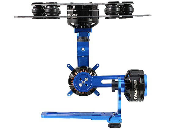
Overall, I'm impressed with the quality of both the gimbal frame and the brushless gimbal controller.
Gimbal assembly is straightforward, but the brushless gimbal controller setup is rather challenging. Don't worry, I'll walk you through the setup in the Gimbal Controller Setup section.
Review
Parts are all machined and finished well. Everything fit together nicely and there was no play after assembly.
The motors are extremely well built, have 22 poles (the more poles, the better, for a gimbal) and are huge. Checkout this photo next to an 1806 motor:

Frame Build
I measured the included screws and here's what I found. I'm not convinced the M2x8 are actually M2, they're maybe 2.5M? Either way, I'll call them M2x8 in the guide.

Note the M3x7 have countersink heads and the M3x6 are silver.
There are two mounting options here. On the top left, the standard mounting plates for a rail system. There's no rail system on the Q600, so I'll set these aside.

Here's the mounting kit for the Q600 we'll be using.

Lay out the pieces like this. The motors, gimbal controllers and thumb screws will be mounted approximately in these locations.

Start from the top and work down, beginning with the carbon fiber mounting plates.

Begin by using the large vibration dampeners to connect the two circular carbon fiber plates.
Insert them into the one with the larger hole first, three per side.
Protip: wrap a short piece of string around the top of the vibration dampener and loop it through the hole.

Pull the string (don't be afraid to pull hard) and the whole thing will pop through.

You may not need to do this on the first side, but it really helps when connecting the second plate.
Here's how you connect the large 017-100T motor to the top plate.

All the parts are facing forward in this picture, also notice the position of the servo lead solder points. We want those facing toward the back, out of the way.


Let's go ahead and solder those on now. Tin the pads and the leads on each, then hold the pad and lead together while you touch the iron to the lead. The leads can be attached in any order. We can change the direction the gimbal turns in the software configuration step.
Ok, time to bust out the thread lock. I like blue, but use whatever you prefer.

Screw the standoffs onto the vibration dampening plate using the silver M3 screws. Don't worry you may have an extra standoff.

Now let's start building the actual gimbal. We'll work from the top right of our parts layout, down and to the left.

Attach the top frame piece to the bottom of the top motor. The side with the bevelled cut should go away from the motor. Use the countersink screws.

Slide the arm that says ASP onto the piece you just installed, making sure the side with the large screw hole is closest to the "L" shape.

Use some threadlock and install the thumb screw.
Install the next frame component on the back of the next motor. Use the M2x8 screws and threadlock.

Install the next frame component on the front of the same motor. Use the countersink screws.

On the third and final motor, install the prop adaptor on the front, using the countersink screws.

Install the arm on the back using M2x8 screws. I've oriented the motor wires up so they're out of the way in case of a hard landing.

Slide the remaining two pieces together and install the thumb screw through the bottom.


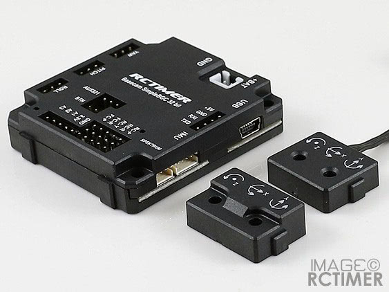
Connect the two sensors like this.

The sensor with two wires will connect to the frame and the other connects to the plate to the left of the camera. Just so you can plan ahead, this is how it will look.

Install the SimpleBGC sensor with the single lead using M2x8 screws. Use threadlock and don't over tighten these.

Now, just use the remaining thumb screws to connect it all together.


Install the Gimbal Controller. I needed to modify the case a little to use the shorter screws I had on hand. I used a hand reamer to open the top screw holes up to 5mm. Alternatively, get longer screws or just take off the plastic case.

If you do take apart the plastic case, don't lose the tiny button. Re-assemble it, upside-down, so you can get the button back in properly.

Screw the SimpleBGC controller onto the frame.

I had to shorten the wire on the sensor with a single lead down to 30mm. Just cut and re-solder.

I'll mount this one to the quadcopter frame so the yaw axis can be controlled by the SimpleBGC controller without any input from the Flight Controller.
If you mount it to the gimbal frame, it will help correct dift instead.
I installed the single-wire sensor on the carbon fiber under body of the Q600 using a piece of double sided tape and a zip tie.

Whoops, broke the white zip tie. I'll use a black one instead.

Install the mounting plates with the sensor to the standoffs on the assembled gimbal using the M2x8 screws.

Clean up your wires with some zip ties, while ensuring that the gimbal can rotate to the endpoints you want to be able to reach. Coiling up the wire also helps keep things neat.

Gimbal Balance and Calibration
The first step to getting good performance out of your gimbal is to ensure that it is well balanced. The basic idea is to mount the camera to the gimbal and turn on the camera, so the lens is extended. Then, check that each axis rests easily when placed level, much like balancing a propeller.
Here's a good video guide:
Gimbal Controller Setup
You'll want to update your SimpleBGC to the latest firmware.
Download the latest version of the SimpleBGC GUI from this page https://www.basecamelectronics.com/downloads/32bit/.
Extract the zip file.
Windows
On Windows, just run the .exe file.
Skip to SimpleBGC Flashing.
Mac
On my mac I had to open terminal, cd into the extracted folder and edit run.sh in a text editor, replacing the javaw command with java.
In the SimpleBGC readme, it says to create a lock file directory. Do not skip this, if you do, flashing could fail. In a terminal window, run:
sudo mkdir /var/lock
Enter your password when prompted, then set the permissions on the directory to allow SimpleBGC to use it with:
sudo chmod 777 /var/lock
Change permissions on run.sh to allow it to be run with:
chmod +x run.sh
Then run the program with: ./run.sh
SimpleBGC Flashing
Find a micro USB cable you have lying around and plug in the Basecam SimpleBGC 32-bit gimbal controller.
Under Connection: find your serial port and hit connect

If you get a message saying the firmware is out of date, hit OK

Go to the upgrade tab

Click Check for a new version

Hit Go to upgrade

I hit skip when prompted for my email

Then I hit Upgrade! and it failed. Oh no, "Failed to upload: Error writing firmware: ... Permission denied" :(

I didn't create the lock file before I ran SimpleBGC the first time. If you're like me, unplug your board, close SimpleBGC, create the lock file directory with sudo mkdir /var/lock then set the permissions with sudo chmod 777 /var/lock
Now start over at SimpleBGC Flashing
When you get back to this step, after configuring SimpleBGC in the terminal, you should see a message that says flashing then a message that says the firmware updated successfully.
Time to configure the gimbal controller.
SimpleBGC Setup
After flashing, I had to unplug the USB to the board, close SimpleBGC and re-open it by running ./run.sh in my terminal.
Under Connection: find your serial port and hit connect.
The beeper is really annoying when working on the SimpleBGC, so I turned it off. Just uncheck the Buzzer boxes on the Service tab and hit write.

On the Basic tab, click Swap frame and main sensor, then click write

Let's tell the controller how our sensors are oriented.
Camera IMU is set to Axis TOP: Z, RIGHT: -Y
Frame IMU is set to Axis TOP: -Z, RIGHT: X

If you mounted yours differently, just hit AUTO for each sensor and follow the guide.
Make sure that you tell SimpleBGC the Frame IMU is on the quad-copter frame by setting Frame IMU: Above YAW

Also, make sure that on the RC tab, the Input Mappings are all set to no input you can adjust this later if you're using a remote control to steer the gimbal.

Next, turn down all the PIDS values to 0. E.g. to P: 0, I: 0, D: 0 for all three axis.
Then turn down the motor power. See the screenshot below of what worked for me.
Next, we'll figure out if any of the motors need to be inverted. Plug a battery into the back of the camera. I used a little 3S battery. Then hit AUTO under the Motor settings.
Make sure the poles are set to 22 on all motors and hit Write at the bottom of the app.

Calibration
In SimpleBGC GUI, go to the basic tab and hit the IMU Calibration Help button.

You'll see this screen:

Make sure you've powered down the board and re-started it since swapping the Frame IMU and Camera IMU. If the board has been power cycled, the sensors should now have the right names (Frame IMU on the frame and Camera IMU on the camera).
Hold the camera mount in place, I used a table, pick Frame IMU and hit calibrate. It's crucial the IMU is as still as possible while calibrating.

Repeat the process, moving the IMU to every 90-degree orientation.

Then do the same with the frame IMU, but pick Camera IMU in the configuration tool.

When you're done, set the gimbal on a steady surface, go to the monitoring tab and make sure the traces look stable.

In SimpleBGC GUI, you'll notice these gauges on the right:

There is one gauge for each axis. The red ball tells you which way the gimbal is trying to point.
The red balls on several axes were spinning, so I set the camera on a chair like this. I then calibrated the gyro again (Basic tab -> Sensor section -> IMU Calibration Help...)

When the gimbal is completely still, hit Reset then Calibrate in the Gyroscope section. It will calibrate both gyros at once.

Make sure the camera is level and perfectly still while calibrating.
If, under the basic tab, you set Sensor -> Gyro calibration -> Calibrate on system start this will do the same thing every time you power on the gimbal.
Tuning
Note that to get good PID values during tuning, your setup must be as close as possible to what you'll be flying with, so use the same power supply that you'll be using during normal operation.
Make sure the power settings and the PIDS are all turned down to 0. On the roll axis, set power to 150, hit write, then click AUTO pick only the roll axis and start from 0.
My final values for roll are:
P: 25
I: .13
D: 10
Now turn on the camera so the lens extends (this is how the gimbal should have been balanced), then set the power to 90 on the pitch, hit write and auto tune the pitch axis.
Pitch values are:
P: 8
I: .13
D: 4
Finally, set the power to 90 on the yaw axis, write and autotune the yaw axis.
The yaw values autotune found are:
P: 19
I: .05
D: 15
I had a little bit of buzzing, so I then went back and re-tuned roll using the same steps as above.
The roll values autotune found the second time are:
P: 25
I: .13
D: 10
If you still have a bit of buzzing, retune the problem axis. You may try moving the gimbal into the position that causes the vibration and then re-tuning again. The autotune feature works by adjusting the PIDs until they vibrate, then turns them down a bit. So, putting it in the condition that makes it vibrate may help.
My power settings are:
Roll:  145 + 0
Pitch: 95 + 0
Yaw:   95 + 0
Finally, I checked the box next to Follow YAW and turned YAW SPEED up to 25. This will make the camera turn when I turn the quad-copter.

Gimbal Troubleshooting
If the gimbal isn't performing properly, here are some troubleshooting tips.
-
High-frequency vibrating
-
The power for a given motor could be too high
-
Check
Dfor the axis you think is vibrating, it could be too high -
Check
Pfor the axis you think is vibrating, it could be too high
-
-
Camera is jumping around wildly
- P is too high for the power
-
Buzzing
-
A motor has too much power
-
Check the
AdvancedtabTimingssetting, make surePWM frequencyis set toHigh
-
Further Reading
For more gimbal controller fun, download the latest manual here: https://www.basecamelectronics.com/downloads/32bit/
Here is an awesome gimbal configuration and setup guide. Even better, the music is awesome: https://www.youtube.com/watch?v=NWj7EojEVnA
Continue onto the PixHawk Flashing and Setup guide or back to the Q600 Build.